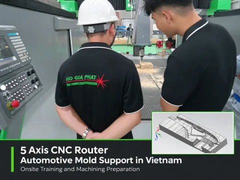

BCAMCNC provided onsite technical support for a customer in Vietnam, with automotive mold development as an application focus. The project included CAD models of dashboard mold components, alongside practical five-axis machining trials and machine operation guidance.
Automotive dashboard tooling combines broad curved surfaces with recessed features and changes in machining direction. Preparing these parts requires a coordinated approach to model review, tool access, workholding, and machining strategy.
The onsite work connected these application requirements with the operation of the 5-axis CNC router, providing a practical foundation for further mold machining preparation.
Understanding the Dashboard Mold Geometry

Reviewing curved surfaces and recessed features
The supplied dashboard mold designs included elongated curved sections, pockets, and transitions between surfaces. These features require different cutting approaches across the part.
Broad surfaces may be accessible with a vertical tool, while steeper walls or restricted areas can require an inclined approach. Before programming, the mold geometry needs to be reviewed together with the proposed stock, cutting tools, and fixture arrangement.
This review helps determine which areas can be machined directly and which require a different tool orientation or an additional operation.
Planning Tool Access with Five Axis Movement

Considering the tool, holder, and spindle head together
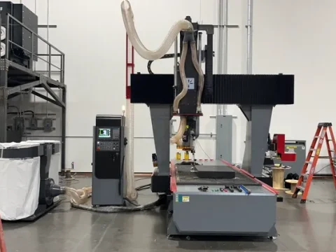
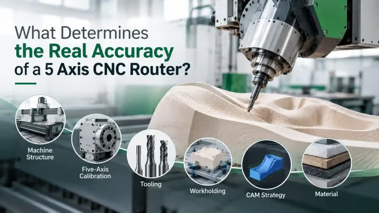
A five-axis CNC router allows the cutting tool to approach the workpiece from different angles. For dashboard mold components, this provides more options for reaching curved transitions and selected recessed areas.
The advantage depends on the geometry and setup. Tilting the tool may improve access, but the entire spindle assembly must have sufficient clearance around the workpiece and fixtures.
Tool length also needs careful consideration. A longer tool may reach deeper features, while a shorter tool generally offers greater rigidity when access permits. The machining plan must balance reach, clearance, and cutting stability.
Preparing the Mold Machining Sequence
Separating stock removal from surface finishing
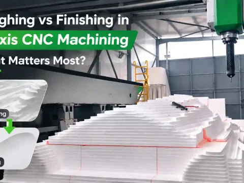
Dashboard mold machining benefits from a clear sequence of roughing, intermediate machining, and finishing.
Roughing establishes the overall form while leaving material for later operations. Intermediate machining removes remaining stock in areas that larger tools cannot reach. Finishing then follows the required geometry more closely.
For curved mold surfaces, tool shape, stepover, and cutting direction influence the resulting surface texture. Changes between adjacent machining regions also need attention to avoid visible marks or uneven finishing allowances.
The final strategy must be developed for the actual tooling material and the surface requirements of the next manufacturing stage.
Using Trial Machining to Establish the Operating Process

Validating machine functions before a complex mold job
During the Vietnam visit, a wooden test block was used for practical machining trials. The work included vertical and inclined tool approaches, allowing the team to follow changes in spindle orientation around a manageable workpiece.
These trials addressed machine operation and movement. They were a preparation step, separate from machining the dashboard mold components supplied as CAD models.
Using a simple test piece made it easier to explain the relationship between the program, tool position, and fixture clearance before progressing to more demanding geometry.
Coordinating Tool Changing and Controller Operation

Linking tool preparation with the mold program
The onsite support also included automatic tool changing and guidance at the CNC controller.
A mold program may require several tools for stock removal, surface finishing, and smaller details. The tool selected in the program must correspond with the physical tool and its recorded data.
Working through the tool-changing sequence at the machine helped connect these preparation tasks with practical operation. Controller guidance further linked the displayed program information with the machine’s response.
Supporting the Next Stage of Automotive Mold Development
Moving from CAD geometry toward a verified machining setup
The Vietnam project brought together automotive dashboard mold designs and practical five-axis machine instruction.
The CAD models defined the application geometry. The machining trials addressed the equipment functions needed to prepare and run a job. Together, they provided a basis for further work on CAM programming, tool selection, stock preparation, and machining verification.
For automotive mold development, this preparation is essential. Machine capability delivers value when it is matched with a suitable process for the actual part.
Discuss Your Automotive Mold Machining Requirements
Start with the model, material, and intended use
Send BCAMCNC your automotive mold drawings or 3D models, stock material, workpiece dimensions, and surface requirements.
These details help identify the required working envelope, tool access, machine configuration, and technical support needs for your application.
Website: https://www.bcamcnc.com
Email: admin@bcamcnc.com
WhatsApp: +86 151 5410 9683