
Why UAV Manufacturers Are Moving Composite Machining In-House
In many UAV factories, the biggest production bottleneck is not flight control development or battery integration. The real pressure often appears later, when prototype airframes move into physical manufacturing.
This is especially common in projects involving fixed-wing UAVs, VTOL platforms, and composite airframes with large aerodynamic surfaces. At that stage, manufacturers usually begin facing a series of practical production problems:
carbon fiber edges become inconsistent after manual trimming, outsourced molds take too long to modify during prototype iterations, large foam models lose symmetry after repositioning, and thin composite skins deform during drilling or slotting.
These are not theoretical engineering discussions. They are typical shop-floor issues that directly affect prototype cycles, assembly consistency, and delivery schedules.
Over the past several years, more UAV manufacturers have started bringing these processes in-house instead of depending entirely on outsourced mold shops or manual composite trimming teams. In many of these projects, the equipment being evaluated is not a heavy aerospace machining center, but a large-format 5-axis CNC router designed for composite materials, tooling board, foam structures, and lightweight aluminum fixtures.
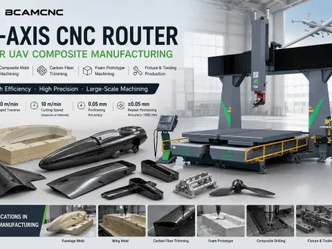
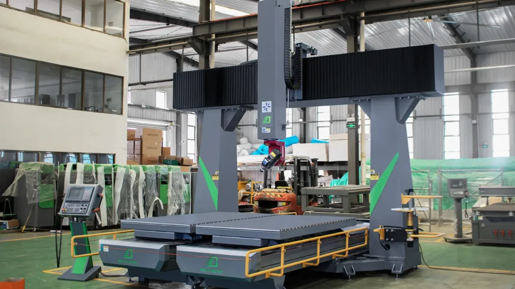
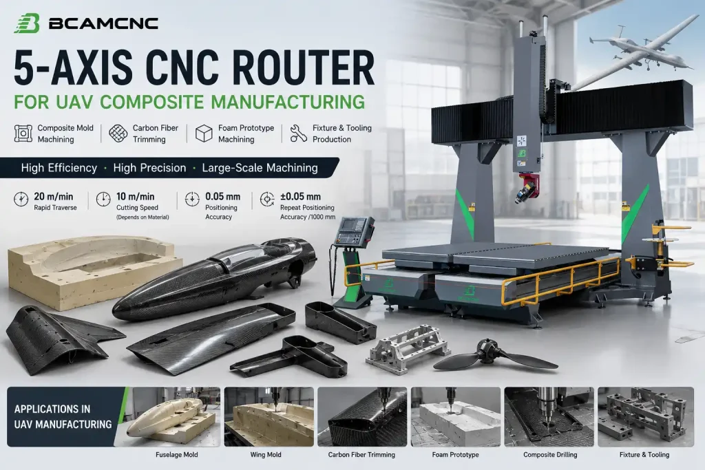
At BCAMCNC, most UAV-related inquiries around the D Series 5-Axis CNC Router are connected to four practical applications:
- composite mold manufacturing,
- carbon fiber trimming,
- foam prototype machining,
- and assembly fixture production.
The reason is relatively straightforward. UAV manufacturing often involves large curved geometries, lightweight structures, and multiple prototype revisions. In these situations, simultaneous 5-axis movement is less about “high-end machining” and more about reducing repositioning errors, maintaining stable tool orientation, and shortening production iteration time.
At the same time, realistic expectations are important. A 5-axis CNC router is not intended to replace heavy-duty aerospace metal machining centers. Its effectiveness depends heavily on material type, fixture strategy, cutting load, and process planning.
Why the D Series 5-axis CNC route Is Commonly Selected for UAV Applications
For UAV composite production, machine rigidity and travel size are usually more important than extreme metal-cutting torque.
Many drone airframe molds and wing structures are physically large but relatively lightweight. This changes the machine requirement completely compared with traditional steel machining.
The D Series is typically configured for:
- large-format composite molds,
- foam prototype structures,
- carbon fiber trimming,
- and long aerodynamic surface machining.
In practical production environments, the machine commonly operates with:
- rapid traverse speed up to 20 m/min,
- processing speed around 10 m/min depending on material and cutting strategy,
- and foam machining speeds that may reach approximately 8 m/min under suitable roughing conditions.
The machine positioning accuracy is specified at 0.05 mm, with repeat positioning accuracy controlled within ±0.05 mm / 1000 mm.
However, experienced composite manufacturers usually understand that actual part accuracy depends on far more than machine specifications alone.
Large foam structures may still expand slightly with workshop temperature changes. Thin carbon fiber skins may flex if vacuum support is uneven. Long wing molds can accumulate small deviations if fixture positioning is unstable over several meters of travel.
For this reason, in UAV manufacturing, process consistency is often more important than theoretical laboratory tolerance values.
Why Carbon Fiber Trimming Becomes Difficult as Production Volume Increases
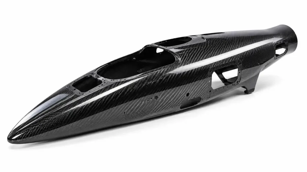
Carbon fiber UAV fuselage shell with precision trimming and panel cutouts
Many smaller UAV manufacturers initially trim carbon fiber parts manually.
At prototype stage, this approach may appear manageable. However, once production volume increases, manual trimming often creates inconsistency between batches. Edge quality begins to vary between operators, assembly holes drift slightly from nominal positions, and post-processing time becomes difficult to predict.
This is especially noticeable on:
- curved fuselage shells,
- wing skins,
- honeycomb sandwich panels,
- and thin composite covers.
Unlike aluminum, carbon fiber reinforced polymer does not behave like a uniform material during machining. The laminate structure reacts differently depending on fiber orientation, resin content, tool wear, and cutting direction.
When the cutting angle is unstable, the tool may begin pulling fibers upward instead of shearing them cleanly. The result is usually edge burrs, local delamination, or visible fiber tearing around drilled holes.
This is one reason why many UAV manufacturers move toward simultaneous 5-axis trimming rather than conventional 3-axis routing.
With 5-axis movement, the cutter orientation can continuously adapt to the surface geometry. Instead of forcing the tool vertically into every curved section, the machine can maintain a more stable cutting angle relative to the laminate surface.
In practical terms, this often helps reduce:
- edge tearing,
- exit burrs,
- localized delamination,
- and excessive manual finishing work.
Still, no machine completely eliminates composite machining challenges.
Carbon fiber trimming quality remains highly dependent on:
- cutter geometry,
- spindle RPM,
- feed rate,
- compressed air support,
- vacuum stability,
- and dust extraction performance.
In many UAV composite applications, spindle speed typically operates within the 12,000–24,000 RPM range depending on cutter diameter and laminate structure.
Compressed air pressure is commonly maintained around 0.6–0.8 MPa to support pneumatic systems such as:
- automatic tool changers,
- rotating axis brake systems,
- and air-assisted chip evacuation.
These values may vary depending on spindle configuration and actual workshop conditions.
Why Large UAV Molds Are Difficult to Maintain Accurately
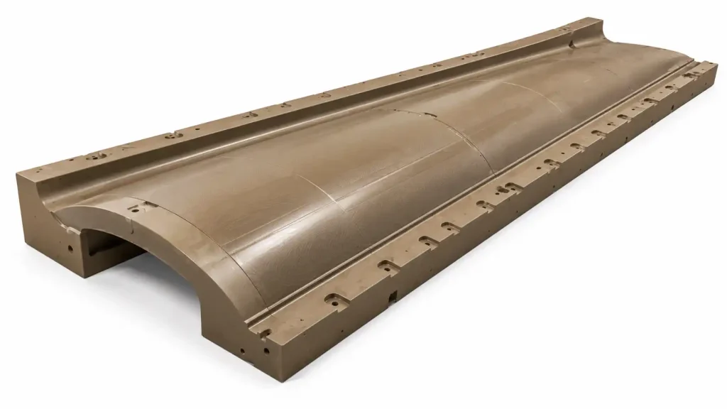
Large fixed-wing UAV wing mold machined from epoxy tooling board
One of the most underestimated challenges in UAV production is large-format mold consistency.
When manufacturing fuselage molds, wing molds, radomes, or aerodynamic nacelles, many parts extend across long travel distances while still requiring smooth surface continuity.
On traditional 3-axis equipment, operators often need to reposition the workpiece multiple times. Every repositioning step introduces the possibility of accumulated deviation.
Even small alignment errors can later appear as:
- visible witness lines,
- aerodynamic asymmetry,
- or assembly mismatch between left and right mold sections.
This is where simultaneous 5-axis machining provides practical value.
Instead of repeatedly flipping or indexing the workpiece, the machine can maintain continuous surface tracking while adjusting tool orientation dynamically across curved geometries.
For UAV mold production, this usually improves:
- surface continuity,
- machining consistency,
- and repeatability between mold halves.
However, realistic process limitations still exist.
Even with simultaneous 5-axis machining, large composite molds normally still require manual sanding and surface preparation before final production use. This is particularly true for:
- high-gloss mold surfaces,
- vacuum infusion tooling,
- and composite layup molds requiring cosmetic surface quality.
In actual production environments, the final surface finish is affected not only by the machine itself, but also by:
- CAM finishing strategy,
- cutter condition,
- fixture rigidity,
- workshop temperature,
- and operator finishing process.
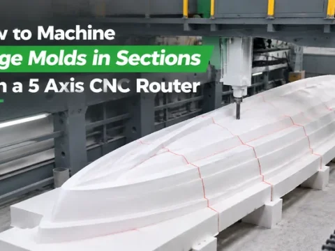
Foam Prototype Machining and Rapid UAV Development
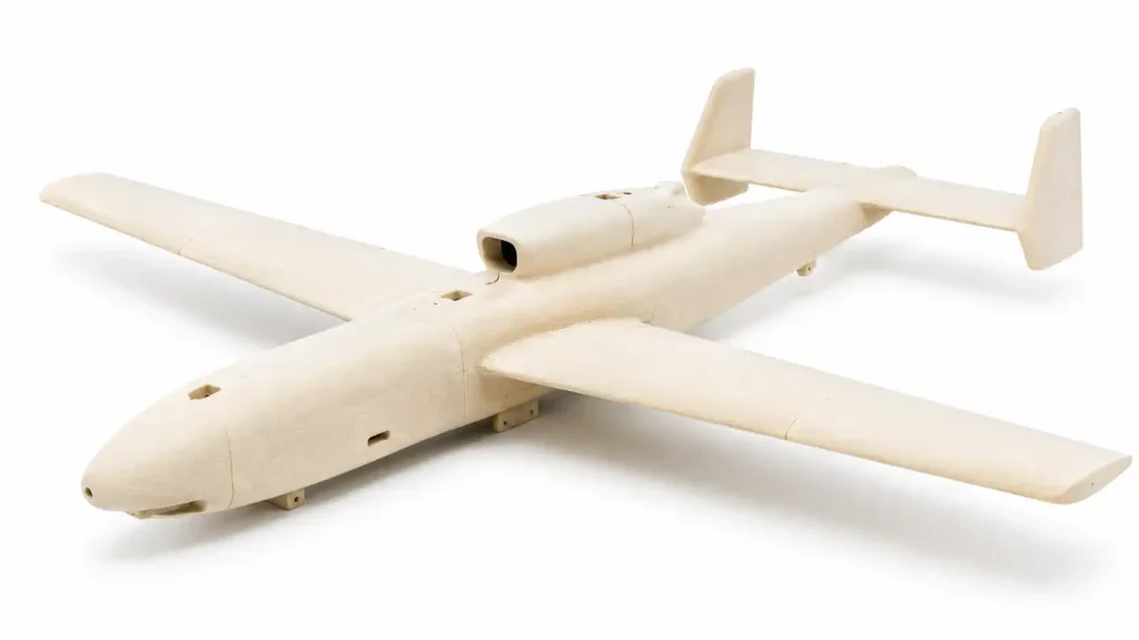
High-density foam UAV prototype model for aerodynamic testing
Prototype iteration speed has become increasingly important in UAV development.
Research teams frequently need to verify:
- airframe geometry,
- aerodynamic surfaces,
- internal component layout,
- and structural concepts before mold production begins.
For this reason, many UAV manufacturers machine foam prototypes or wind tunnel models before committing to final tooling.
Typical materials include:
- EPS foam,
- PU foam,
- synthetic tooling board,
- and lightweight modeling materials.
Compared with dense composite machining, foam processing introduces different challenges.
The issue is usually not cutting force. Instead, manufacturers often struggle with:
- maintaining surface smoothness across large curves,
- preventing vibration on thin sections,
- and avoiding dimensional variation caused by foam elasticity.
In deep cavity machining, the actual limitation is often tool reach and spindle clearance rather than table size itself.
Long tools may begin to deflect during aggressive roughing, especially on deep fuselage cavities or wing-root structures. Excessive acceleration can also create visible toolpath marks on lightweight foam materials.
This is why practical machining speed depends heavily on material behavior rather than advertised machine speed alone.
Although the D Series rapid traverse speed reaches 20 m/min, actual cutting speed is adjusted according to:
- foam density,
- cutter diameter,
- machining depth,
- and surface finish requirements.
For many large UAV foam structures, roughing speed around 8 m/min is more realistic for maintaining stable surface quality during continuous machining.
Why Dust Control Becomes a Structural Requirement in Composite Workshops
Composite machining environments behave very differently from standard woodworking or plastic routing workshops.
Carbon fiber and fiberglass dust are both abrasive and electrically conductive. If fine particles migrate into guide rails or electrical cabinets, long-term machine stability may deteriorate rapidly.
In some workshops, insufficient dust management becomes the actual cause of premature maintenance problems rather than spindle wear itself.
For this reason, dust extraction in UAV composite machining is usually treated as part of the machining process rather than an optional accessory.
Machines configured for carbon fiber production are often equipped with:
- spindle-mounted extraction hoods,
- sealed protective structures,
- and centralized vacuum extraction systems.
Mechanical components exposed to airborne composite particles may also require additional protection to reduce contamination of:
- bearings,
- linear guides,
- encoder systems,
- and rotating axis assemblies.
In long-term composite production, workshop cleanliness directly affects machine lifespan and machining consistency.
Why Fixture Strategy Matters More Than Many Buyers Expect
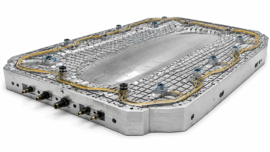
Vacuum suction fixture for UAV composite trimming applications
Large UAV structures are often thin, flexible, and difficult to clamp mechanically.
Traditional edge clamping methods may deform composite skins or interfere with multi-axis tool movement.
This becomes especially problematic during:
- wing trimming,
- fuselage slotting,
- and large curved shell drilling.
As a result, many UAV manufacturers eventually move toward:
- zoned vacuum systems,
- dedicated positioning fixtures,
- resin support tooling,
- and custom vacuum jigs designed around specific airframe geometry.
In practice, fixture quality often determines whether machining repeatability remains stable over long production runs.
Even a highly accurate machine cannot maintain consistent trimming quality if the composite structure shifts slightly during cutting.
This is one reason experienced UAV manufacturers evaluate:
- workholding,
- dust extraction,
- tooling strategy,
- and CAM workflow together,
instead of evaluating only spindle power or machine travel.
Understanding the Real Role of a 5-Axis CNC Router in UAV Manufacturing
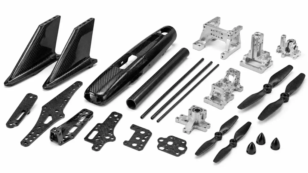
Finished UAV structural components including carbon fiber and aluminum parts
A 5-axis CNC router is most effective in UAV manufacturing when the production focus involves:
- composite molds,
- carbon fiber trimming,
- foam prototypes,
- aerodynamic surfaces,
- and lightweight fixture production.
It is not designed for deep steel roughing or heavy titanium machining. Attempting to use a large-format gantry router for extreme metal removal usually introduces vibration, chatter, and premature tool wear.
But for composite-intensive UAV production, the value of 5-axis machining is often very practical:
- fewer repositioning steps,
- more stable trimming angles,
- improved repeatability,
- shorter prototype cycles,
- and more consistent aerodynamic surfaces.
In many UAV projects, the real goal is not achieving the smallest theoretical tolerance number.
The real goal is maintaining stable production consistency while reducing manual correction work across repeated prototype and composite manufacturing cycles.
That is where a properly configured 5-axis CNC router usually provides the greatest long-term value.